Electric vehicles have the potential to make the world a better place. In IC engine vehicles and electric vehicles and a further two-wheelers and four-wheelers, where the complexities in controls are drastically different, the common technology thread between them is a humble electronic component, the Electronic Control Unit. Several features, widely integrated in four wheelers may include engine immobiliser, motor control unit, powertrain control, brake control, ABS, anti-theft alarm door control, human-machine interface and what not! However, here the focus would be on the electric race car motor control design and corresponding shutdown circuit and system.
The motor control unit, in simple words, is meant for configuring the motor speed and torque after receiving comments from the Electronic Control Unit (ECU) via CAN-bus and other modes of communication.
An EVM controller or electric vehicle motor controller is a machine that is employed to regulate the torque generated by the motors of electric vehicles by means of modifying the energy flow from the power source to the motor.
The controller takes power from the accumulator and delivers it to the motor. The accelerator pedal hooks to a pair of potentiometers (variable resistors), and these potentiometers provide the signal that tells the controller how much power it is supposed to deliver. There are two potentiometers for safety’s sake. The controller reads both potentiometers and makes sure that their signals are equal. If they are not, then the controller does not operate. The signals to motor controller are checked through a microcontroller unit implemented on a PCB design to guard against failure or fault case situations. Others faults such as Brake System implausibility, isolation break in HV and LV, high accumulator temperature, pedal wire breaks, etc are also monitored through the design.
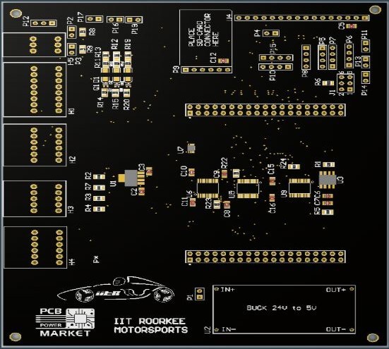
In any case of fault, the motor controller, and hence the motor is disconnected from the accumulator. The design thus involves a shutdown circuit for isolation of motor controller and accumulator, which involves a precharge and a discharge circuit for pre-charging and discharging of motor controller DC-link capacitor, HVD interlocks, and a shutdown control circuit which encompasses the PCB relays and other shutdown switches, inertia switch and user switches for controlling the shutdown circuit operations.
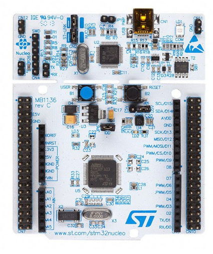
We develop and design our own control algorithms for controlling signals from PCB and microcontroller to the motor controller, using softwares like Altium designer, LTSpice, MATLAB, and the MBed platform for microcontroller Nucleo boards. PCB soldering, assembly and testing are the next important phases involved in the process.
Our aim is the optimization of everything to get the best lap-time in a racetrack while ensuring full safety of the driver at the same time, and we go on overcoming more and more challenges in the field.
 Our Data Acquisition System (DAQ)